Pneumatic piercing can make a short water, gas, conduit, or service-line crossing compact and efficient, but only when the route suits an unsteered displacement tool. The useful question is not whether the bore is short. It is whether the ground, cover, utility corridor, pit geometry, product, and recovery options leave enough tolerance for a tool whose path is largely determined at launch.
Before comparing GRUNDOMAT pneumatic piercing tools, define those constraints. A model that appears to match the pipe diameter can still be unsuitable because it demands more cover, airflow, handling capacity, or recovery space than the site provides.
The selection process should move in one direction: screen the crossing, specify the complete operating package, prove delivered air under load, and keep another installation method available when steering or direct exposure is more valuable than a small surface footprint.
Screen the Crossing Before Selecting a Tool
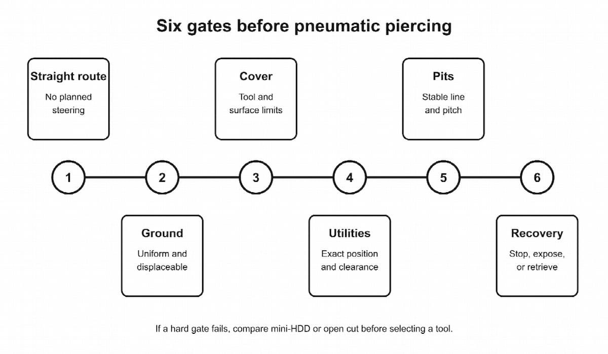
Pneumatic piercing works by repeatedly driving a tool through the ground and displacing soil around its body. It does not create a tracked pilot path, and conventional tools are not steerable after full entry. That makes the launch setup and the ground’s response part of the guidance system.
A strong candidate usually has all of these characteristics:
- a straight route between pits;
- reasonably uniform, displaceable soil;
- enough cover for the tool and expected soil movement;
- verified clearance from existing facilities;
- launch and receiving pits that can hold the required line and pitch;
- a product and pulling arrangement compatible with the bore;
- a safe place to expose or recover the tool if progress stops.
Failing one condition does not always prohibit piercing, but it increases the investigation and control required. Several failures together normally point to mini-HDD or open cut.
Treat Ground as a Path-Control Variable
Uniform cohesive or otherwise displaceable soil tends to support the tool evenly. Variable fill can do the opposite. The body may follow an old trench, a loose seam, or the path of least resistance. Large cobbles, demolition debris, foundations, roots, and dense obstructions can deflect or stop it. Very loose or saturated material may not provide enough grip to maintain the intended line.
A generic soil label is not enough. “Fill” can mean compacted granular backfill or a mixture of brick, concrete, organics, and voids. Review records, inspect nearby excavations, use test holes where they resolve a specific uncertainty, and note transitions along the route. A 30-foot crossing through one consistent formation can be more predictable than a 15-foot crossing through three disturbed zones.
Keep Three Depth Checks Separate
Short crossings often fail at the planning stage because three different dimensions are treated as one:
- Product burial depth comes from the utility owner, code, frost protection, project design, and connection elevations.
- Tool cover is the soil needed above the piercing tool to develop support without unacceptable surface movement. The cited GRUNDOMAT manual uses ten tool diameters as its minimum working-depth guideline.
- Utility clearance is the required separation between the proposed installation and the verified position of existing facilities.
A 3-inch tool implies 30 inches of working depth under the ten-diameter guideline. That figure does not establish the water service’s required burial depth, prove clearance from another utility, or authorize a shallow bore beneath sensitive pavement. Each check must pass independently.
Verify the Corridor, Not Just the Paint
Complete the applicable One Call or 811 process and investigate private, abandoned, and nonmetallic facilities that public markings may not identify. OSHA requires the estimated locations of underground installations to be determined before excavation. As the work approaches them, the exact locations must be established by safe and acceptable means.
Expose critical crossings before the tool reaches them. A pothole or vacuum-excavated observation point can establish horizontal and vertical position and let the crew observe clearance during the crossing. Surface paint alone does not provide depth, diameter, or certainty that every facility has been marked.
The route also needs a consequence check. A slight miss in open lawn may be recoverable. The same deviation beside a gas service, under new pavement, or near a building entrance may be unacceptable. Define the permitted corridor and recovery locations before deciding that the blind process is tolerable.
Specify the Complete Piercing Package
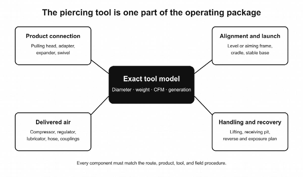
The tool body is only one component. The operating package includes the pulling or expansion attachment, starting level or aiming frame, launch cradle where needed, regulator, lubricator, shutoff valve, couplings, supply and whip hoses, lubricant, handling equipment, and recovery hardware.
Select these parts as one system. Thread compatibility proves that two components connect; it does not prove that the smallest internal passage can carry the required airflow.
Match the Model to More Than Product Diameter
Start with the product outside diameter, joint or coupling profile, wall class, allowable pulling load, bend limitations, and the manufacturer’s approved pulling method. The bore must accept the product and attachment without creating more displacement than necessary. Oversizing raises the volume of soil moved, cover demand, tool weight, and compressor demand.
Representative current North American specifications illustrate why the exact model matters:
| Model | Tool diameter | Tool weight | Published airflow |
| 45 P | 1.75 in | 20 lb | 12 CFM |
| 55 P | 2.0 in | 32 lb | 18 CFM |
| 65 PK | 2.5 in | 40 lb | 23 CFM |
| 65 P | 2.5 in | 55 lb | 25 CFM |
| 75 PK | 3.0 in | 62 lb | 28 CFM |
| 75 P | 3.0 in | 75 lb | 32 CFM |
| 95 P | 3.75 in | 143 lb | 53 CFM |
The 65 PK and 65 P share a nominal 2.5-inch diameter, but their published weight and airflow differ. The 75 PK and 75 P show the same pattern at 3 inches. Diameter narrows the choices; model identity determines the actual handling and air requirements.
Use documentation for the exact generation on the job. P, PK, Servo, S, and P+ designations should not be blended into one specification table. When considering used equipment, confirm the serial identity, head and casing condition, seals, reverse function, hose, couplings, and available manual.
Design the Pits Around Alignment and Recovery
The launch pit must be long and stable enough to establish the required line and pitch. A short pit that forces the tool into position at the last moment sacrifices the main control available to the operator. A starting cradle or alignment frame should rest on a prepared base and remain fixed as the tool enters the ground.
The receiving pit must accept the complete body and give the crew room to disconnect or recover it safely. Tool weight changes the plan quickly: handling a 20-pound model differs substantially from handling a 143-pound model in a confined excavation. Include lifting, access, spoil, trench protection, and safe egress in the pit layout.
Plan for refusal or a missed exit before launch. Identify where an intermediate exposure could be opened, how a reverse-capable tool would be operated under the applicable manual, and when the bore would be abandoned rather than chased. Recovery should be a designed operation, not an improvised response to a tool that has disappeared below pavement.
Inspect the Consumables and Flow Components
An in-line lubricator is an operating component, not a storage accessory. Verify that it is filled with the approved lubricant, oriented correctly, and actually delivering oil before the tool enters the ground. Inspect the supply and whip hoses for damage, contamination, kinks, and internal restriction. Confirm that valves open fully and that couplings have adequate flow area.
TT’s listed basic package includes a 50-foot air-supply hose, in-line lubricator, magnetic starting level, manual, and lubricant with the tool. Additional hose, different pulling hardware, an expander, a cradle, or heavier recovery equipment may still be required by the route. “Package included” is not the same as “project complete.”
Size the Air System for the Tool Under Load
Compressor selection requires both pressure and airflow. Pressure provides the force behind each impact. Airflow sustains the impact cycle. A system can show the expected PSI while stopped and still starve the tool when it begins consuming air.
Use this planning sequence:
- Identify the exact tool’s published air consumption.
- Add every pneumatic tool or device expected to operate simultaneously.
- Apply the manufacturer’s approximately 20 percent allowance for increased demand as seals wear, where that guidance applies.
- Compare the result with the compressor’s sustained output at the relevant working pressure.
- Check the capacity of the regulator, lubricator, valves, couplings, and hose.
- Measure pressure dynamically with the assembled system and tool cycling.
The compressor-capacity guide for pneumatic piercing tools provides a worked version of this calculation. For a 75 P listed at 32 CFM, the seal-wear planning value is 38.4 CFM:
Planning airflow = 32 CFM × 1.20 = 38.4 CFM
If two 75 P tools run together, their combined planning demand is 76.8 CFM before external leaks, restrictive components, other air users, altitude effects, or compressor wear are considered.
The 20 percent factor has a narrow purpose. It addresses increased demand as tool seals wear. It does not excuse a leaking hose, a partially closed valve, an undersized lubricator, or an unknown compressor rating.
Verify Pressure at the Tool
Current TT maintenance guidance specifies a maximum of 95 psi at the tool and 105 psi at the compressor while the tool operates. The exact manual for the model and generation remains controlling.
Do not raise pressure beyond the limit to compensate for missing CFM. A receiver tank can supply a short burst, but it cannot correct a continuous capacity deficit for the duration of the bore. If the compressor produces less air than the tool consumes, pressure will eventually fall.
Measure while the tool cycles, preferably as close to its inlet as the approved procedure allows. Compare compressor and tool readings under the same load. A significant difference directs the inspection toward the air path rather than the compressor nameplate.
Find Restrictions Across the Whole Air Path
Air moves through a series of components:
Compressor ? regulator ? lubricator ? valve ? couplings ? supply hose ? whip hose ? tool
Every restriction creates pressure loss when air flows. Hose inside diameter, total length, coupling bore, regulator and lubricator capacity, contamination, damage, leaks, and moisture all matter. A large main hose connected through a narrow quick coupler still behaves like a restricted system.
Published hose pairings are useful starting points: 1/2-inch supply hose for 45 P through 55 P, 3/4-inch for 65 P through 110 P, 1 1/4-inch for 130 P, and 1 1/2-inch for larger listed Servo tools. Confirm unlisted PK combinations, extensions, and unusual layouts with the manufacturer or supplier rather than extending the table by assumption.
Cold weather creates another operating constraint. Expanding air cools and moisture may freeze within the system. Drain the compressor and receiver, use effective water separation, maintain correct lubrication, and use only approved cold-weather equipment. Additional compressor capacity does not remove water from the air.
Know When Piercing Is Not the Right Method
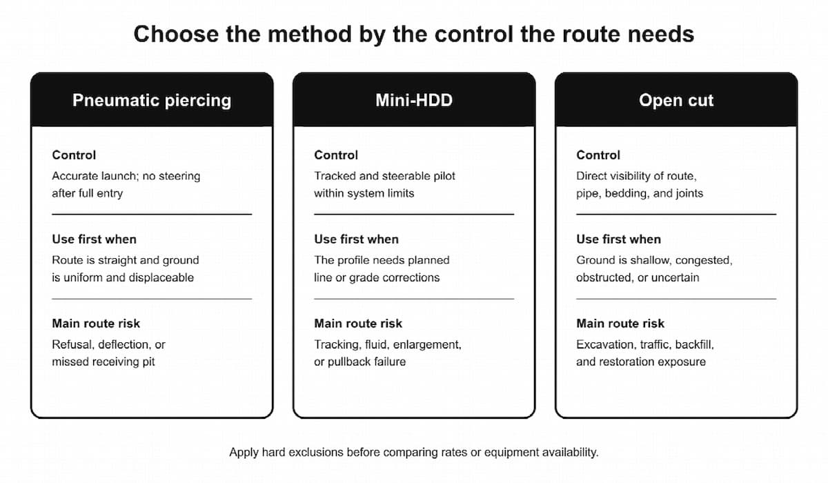
Pneumatic piercing has the smallest process stack only when the route accepts an unsteered displacement tool. If steering, continuous path information, or direct exposure matters more, another method may produce lower total risk.
A practical comparison of pneumatic piercing, HDD, and open-cut trenching frames the choice around the site’s failure modes rather than the nominal crossing length.
| Decision factor | Pneumatic piercing | Mini-HDD | Open cut |
| Path control | Launch determines path; no steering after full entry | Pilot is tracked and steerable within equipment and geometry limits | Alignment is directly exposed |
| Best initial fit | Straight route, suitable soil, adequate cover | Planned corrections or curved profile are required | Shallow, congested, obstructed, or uncertain corridor |
| Main support systems | Compressor, air treatment, hose, pits, pulling and recovery hardware | Rig, locator, tooling, drilling fluid, reaming and pullback systems | Excavator, protective system, spoil, bedding, backfill and compaction |
| Primary route risk | Deflection or refusal | Tracking, fluid behavior, enlargement and pullback | Excavation, traffic and restoration exposure |
| Subsurface visibility | Limited to pits and exposures | Pilot position is tracked; final product remains underground | Full route is visible during placement |
Choose Mini-HDD When the Route Needs Planned Correction
Mini-HDD creates a tracked and steerable pilot bore. It is a better candidate when the route must change line or grade, pass beneath a wider obstacle, or respond to known conflicts along a designed profile.
That control comes with additional constraints. The rig needs sufficient setback to enter at the planned angle and reach depth without exceeding rod or product bend limits. The crew needs a workable locating environment, a soil-specific drilling-fluid plan, containment, reaming and pullback procedures, and verified product loads.
Steerable does not mean exact. Reaming can cut across a curve, and the product can float or settle in an enlarged bore. The pilot log records the tracked pilot path; it does not automatically prove the exact final centerline of the installed service.
Choose Open Cut When Visibility Is the Strongest Control
Open cut exposes the route. The crew can see conflicts, prepare the foundation, inspect joints, place embedment, and compact backfill in controlled lifts. It can be the lower-risk choice in shallow ground, uncertain fill, rubble, tight utility congestion, or a low-value surface where restoration is straightforward.
The tradeoff is a larger surface and worker-protection scope. The plan must address protective systems, access and egress, adjacent loads, groundwater, spoil, traffic, bedding, compaction, and restoration. Under OSHA’s federal excavation rule, trench excavations 4 feet deep or more require safe egress arranged so workers do not travel more than 25 feet laterally. The competent person, soil, depth, water, traffic, and local requirements determine the complete protection plan.
Compare Installed Cost, Not Tool Rates
Piercing often has low mobilization for the right crossing, but a refusal or missed pit can add pavement cuts and recovery excavation. Mini-HDD brings more equipment and trained roles, but steering may reduce alignment risk. Open cut can reduce underground uncertainty while increasing traffic, excavation, spoil, backfill, and restoration work.
Use a complete estimate:
Total installed cost = investigation + mobilization + production + support + restoration + expected failure cost
Include locating, test holes, pits, qualified labor, support equipment, pipe handling, testing, tracer wire, traffic, permits, spoil or fluid disposal, surface restoration, installed-location records, and realistic recovery or abandonment contingencies. There is no national price table that reliably ranks these methods for every short crossing.
Convert the Selection Into a Prelaunch Plan
Once piercing survives the method screen, turn the choice into a field sequence the crew can verify:
- Confirm product material, outside diameter, joints, pulling limit, burial depth, tracer wire, and testing requirements.
- Draw the route, connection elevations, line, pitch, cover, launch pit, receiving pit, and recovery locations.
- Complete public and private utility investigation and expose critical facilities by an approved method.
- Verify ground assumptions and note transitions, fill, groundwater, and potential obstructions.
- Select the exact tool model, head, pulling or expansion attachment, alignment system, cradle, and handling equipment.
- Match the compressor, regulator, lubricator, couplings, hoses, and lubricant to the published requirements.
- Inspect the tool and air system, then run an approved surface test and record dynamic pressure.
- Establish launch marks and independent alignment checks before applying full operating air.
- Define normal progress indicators and stop-work triggers, including abnormal sound, pressure loss, unexpected movement, obstruction, or activity at an exposed utility.
- Define reverse, exposure, recovery, abandonment, and emergency procedures before the tool enters the ground.
- After installation, complete product testing, tracer-wire verification, restoration, and location records.
The prelaunch meeting should establish clear authority to stop the bore. If the tool behaves differently from the surface test, dynamic pressure falls, the route approaches a clearance limit, or an unknown obstruction appears, production should pause for the planned response.
Pneumatic piercing is effective because it removes several systems that mini-HDD needs and avoids the continuous excavation of open cut. That simplicity exists only after the route, tool, air supply, and recovery plan are proven compatible. When those checks fail, changing the method is sound planning—not a failure to use the equipment already available.